QUADIFYRC.COM
  • RC Cars
  • Car of the Month
  • Quad Reviews
  • COUPONS AND DISCOUNTS
  • About & Contact

QUADIFYRC RC Car Review and Upgrade Guides

WL Toys 104001 Beginners Guide: 4 things you MUST DO

30/4/2021

Comments

 
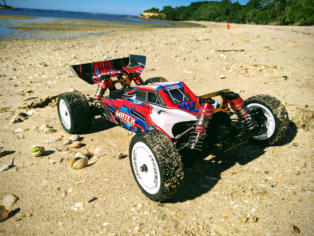
The WL Toys 104001 is an all new car from WL Toys for 2021 that is in the larger 1/10 scale size. Unlike their previous 124019 which is essentially a lengthened 144001, this car is a completely new design. For this reason I will firstly be looking at some tuning that I STRONGLY recommend you complete before even your first run. This is not a review, I'll look to complete that later on once I've spent more time with the car and can give you some thorough feedback rather than an off-the-cuff opinion.
Picture
Just like the 144001 was copied from the LC Racing EMB-1, the 104001 looks to be inspired by the 2016 onwards X-Ray XB4 which is the same basic design to this day albeit with minor improvements year to year. The XB4 is a high end race car and is a strong platform to base design off. However where the XB4 is a no-nonsense race car the 104001 has gone down the basher route so materials and complexity of parts have been downgraded to meet a price point which is more accessible. Whereas race cars need very specific and precise tuning and consumables, bashers tend to be more forgiving however there are some basics you can improve on to enjoy better durability, performance, efficiency and handling. Here I've identified 4 key areas to look at. None of this tuning requires new parts, only consumables.
Picture
​My WL Toys 144001 was ordered from Banggood here
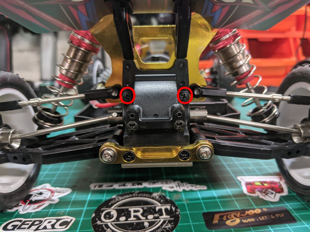
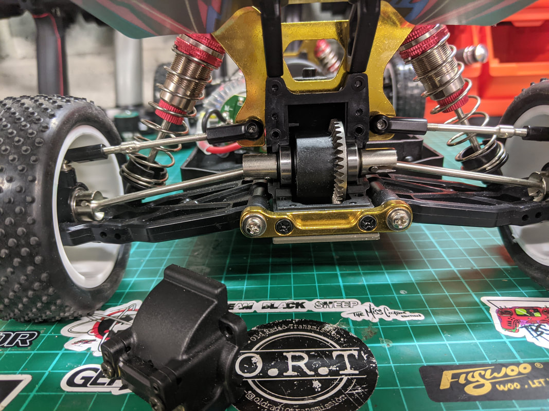
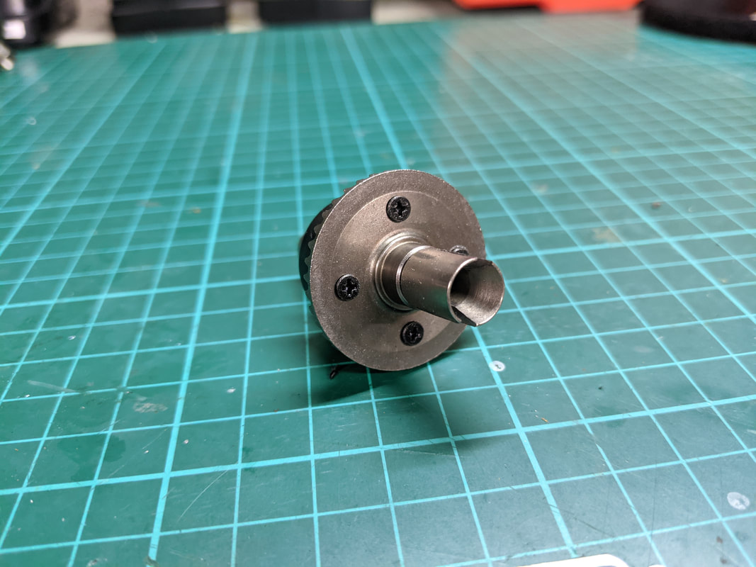
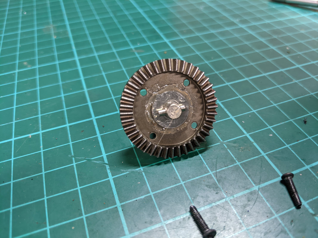
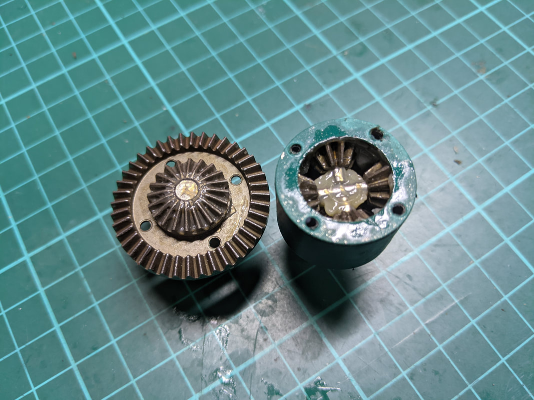
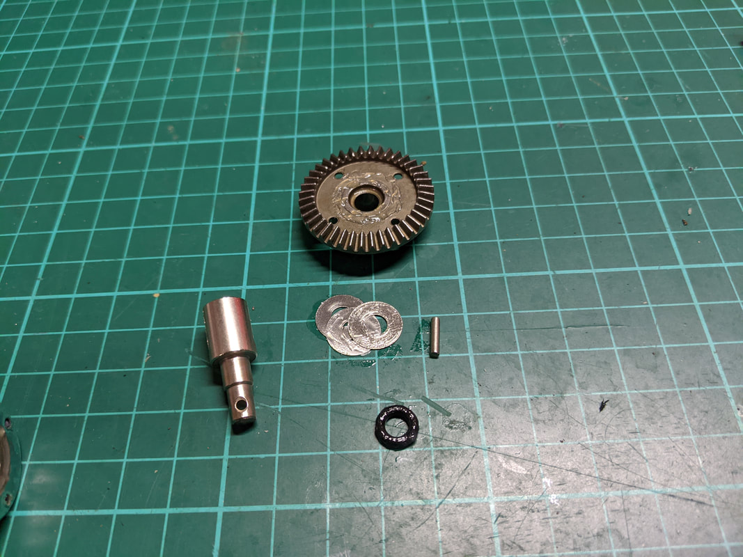
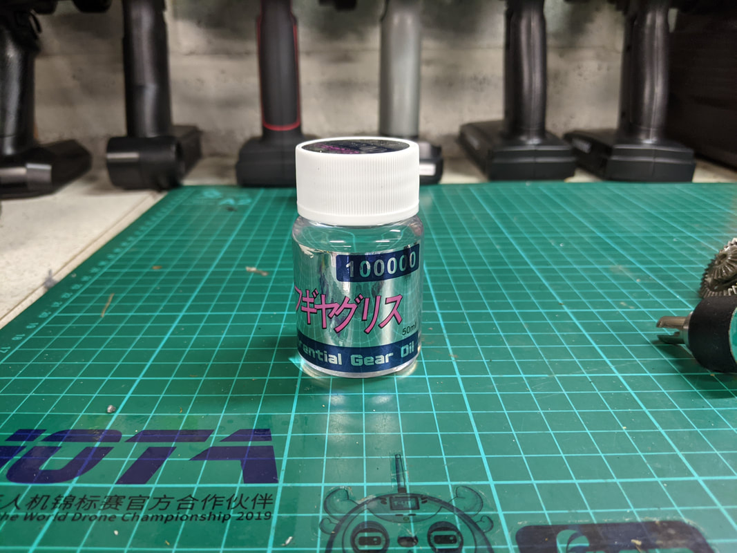
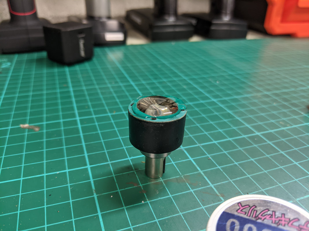
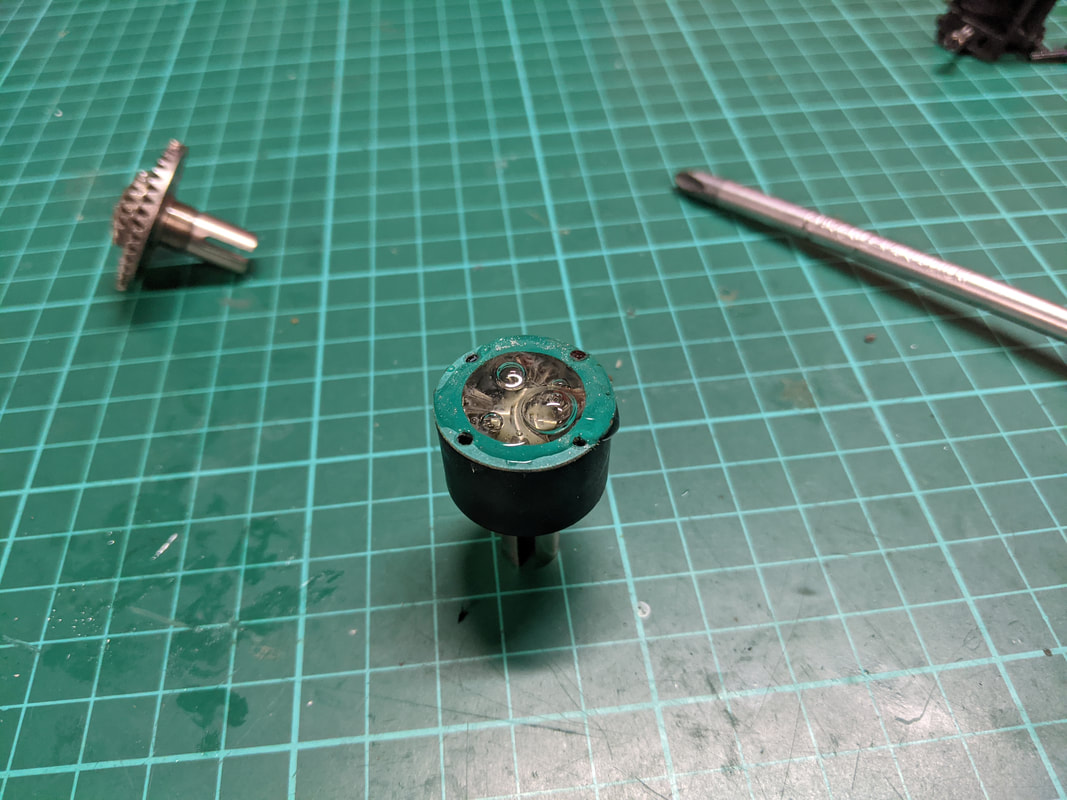
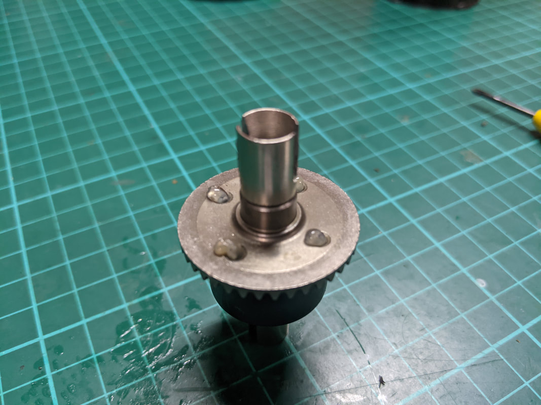
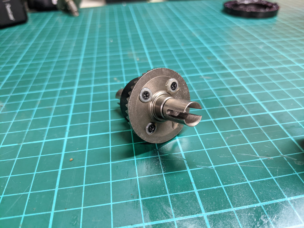
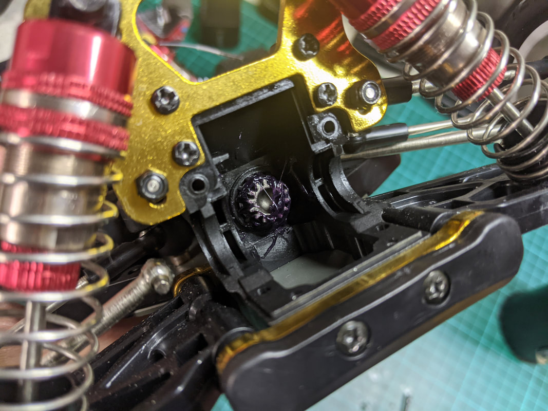
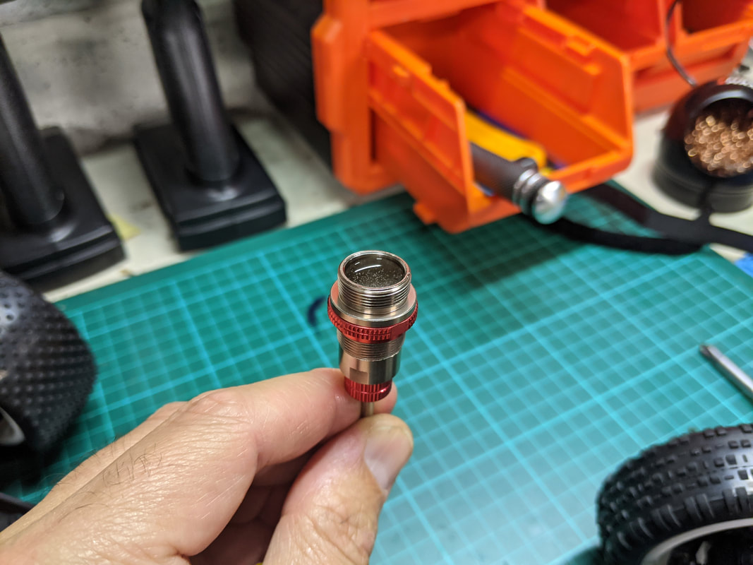
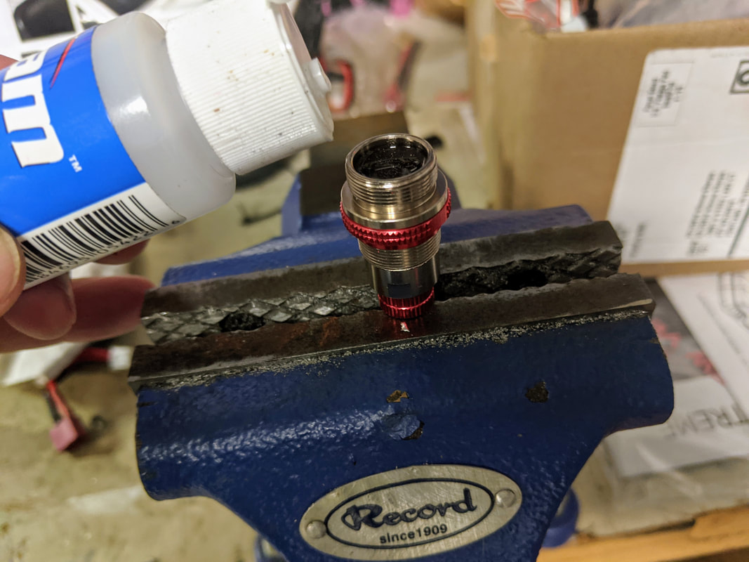
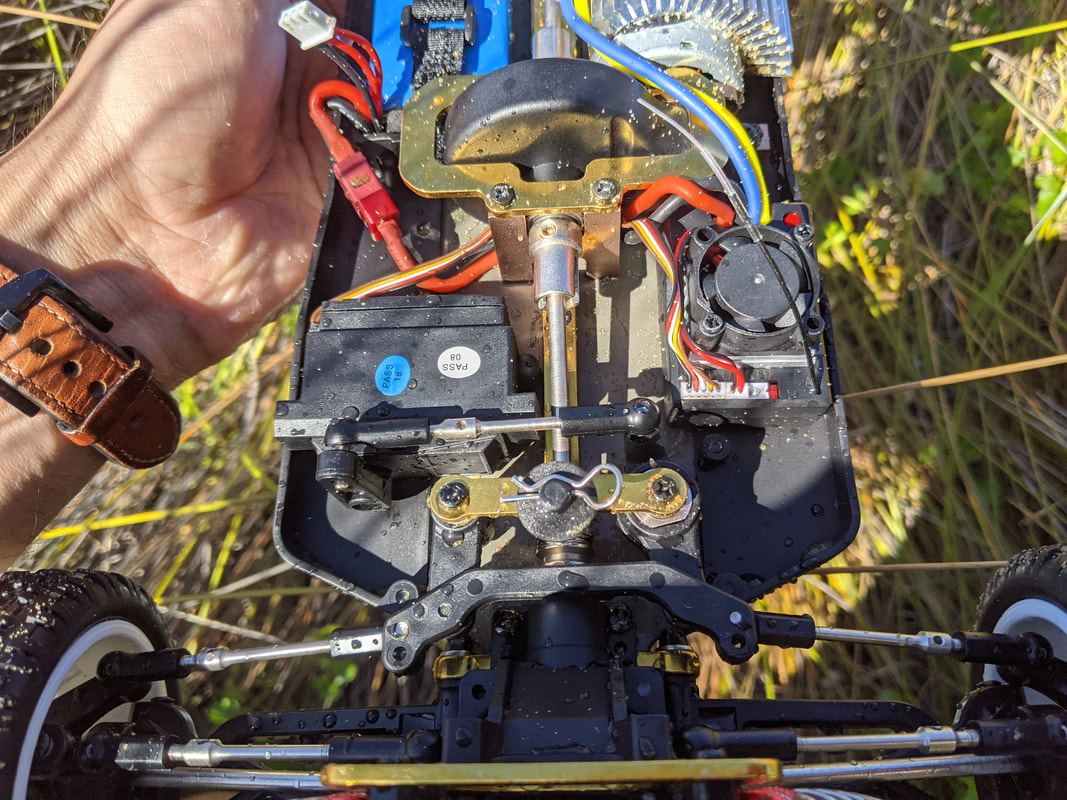
Add Differential Fluid
With the WL Toys 144001 and 124019/18 we added grease to the gears as this semi solid material would attach to the gears within. In higher spec RC cars differentials are sealed with gaskets and o-rings meaning you can use flowing fluids of varying viscosity to tune them. The good news is then that the 104001 does indeed have sealed diffs so we can use a proper diff fluid. I've have chosen to use a 10,000wt fluid which is very much on the thick side. This will create a high level of resistance to the diff spinning and will serve it well on low grip surfaces. If running on high grip surfaces like tarmac, concrete, carpet you'd want to go much lower, say down to 100wt or even the same grade as is used in your suspension. Regardless of what you choose, here is the process for removing the diffs, opening, adding fluid, re-assembling and putting your car back together. This whole process is MUCH easier than the 144001 due to the design improvements they have made.
Picture
1) Remove the M3 screws circled in red above at the front of the car
Picture
2) Remove the 2 long m3 screws circled in red above from the underside at the front.
Picture
3) You should be able to easily remove the front diff cover now. I like this design!
Picture
4) Remove the 2 long m3 screws circled in red above from the underside at the rear.
Picture
5) Remove the M3 screws circled in red above at the rear of the car
Picture
6) Just like the front the rear is super easy to remove. See the diff cover in the foreground here
Picture
7) Take out both front and rear diffs. You'll need to follow these steps for both (which are identical) Undo the 4 small M2 screws.
Picture
8) The large ring gear will com off like this. Don't let the pin fall through but the light coating of grease from factory will keep it in place
Picture
9) Pull the side gear out of the case and pop it back on the ring gear as above. See that green gasket? Sealed Diff!
Picture
10) FYI this is what the ring gear side assembly looks like. O-ring completes the seal and it is well shimmed
Picture
11) I used a 10,000wt oil but this is on the heavy side. Perhaps start with 1000wt or lower for general use. Any RC brand is fine. I Find Team Associated cheapest usually but there is a global shortage of bottle caps at present - being used for sanitiser bottles!
Picture
12) Top the diff up to the rim with the diff fluid. Some like me like to fill to 100%, some to the cross pins, some half. There is no right answer but the more you fill, the more the effect of the oil will be felt. As I say, I prefer 100% full
Picture
13) Wait for the bubbles to come up. This may take 10 minutes with thicker fluids like mine.
Picture
14) Pop the ring gear back on. Excess fluid will come out of the screw holes and that is fine.
Picture
15) Screws back in
Picture
16) Add some grease to the diff pinion gear as pictured since there was no lubrication there at all from the factory
Picture
17) Return diffs to the housing front and rear taking care to add driveshafts to the diff cups. Reverse steps 1) - 6) to reinstall the diff housing covers.
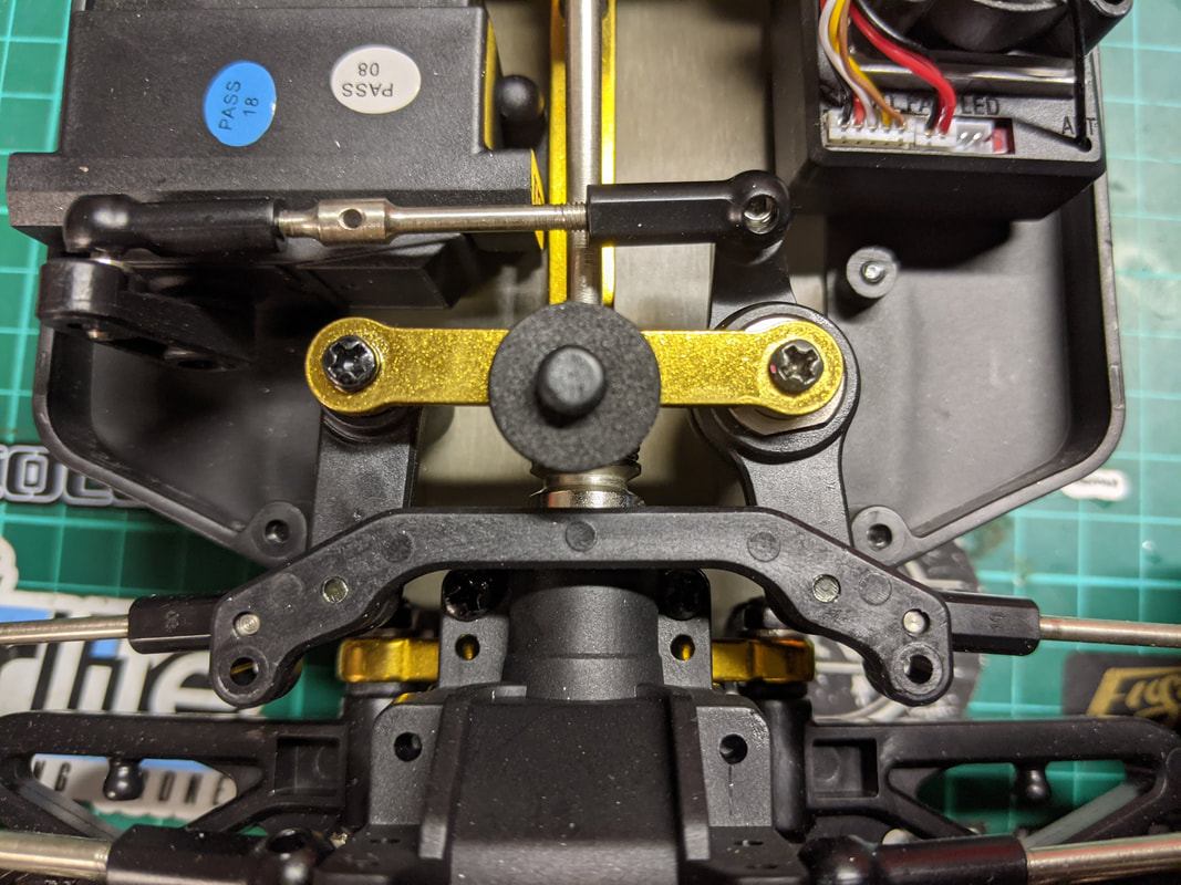
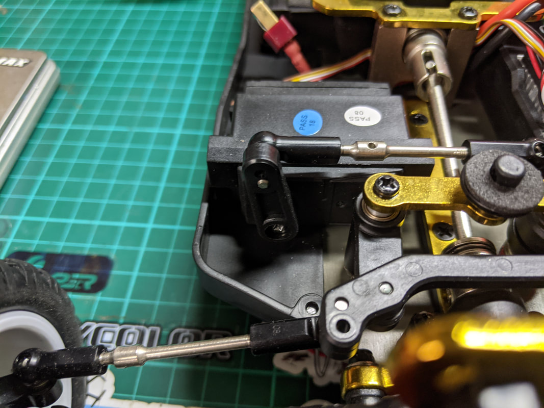
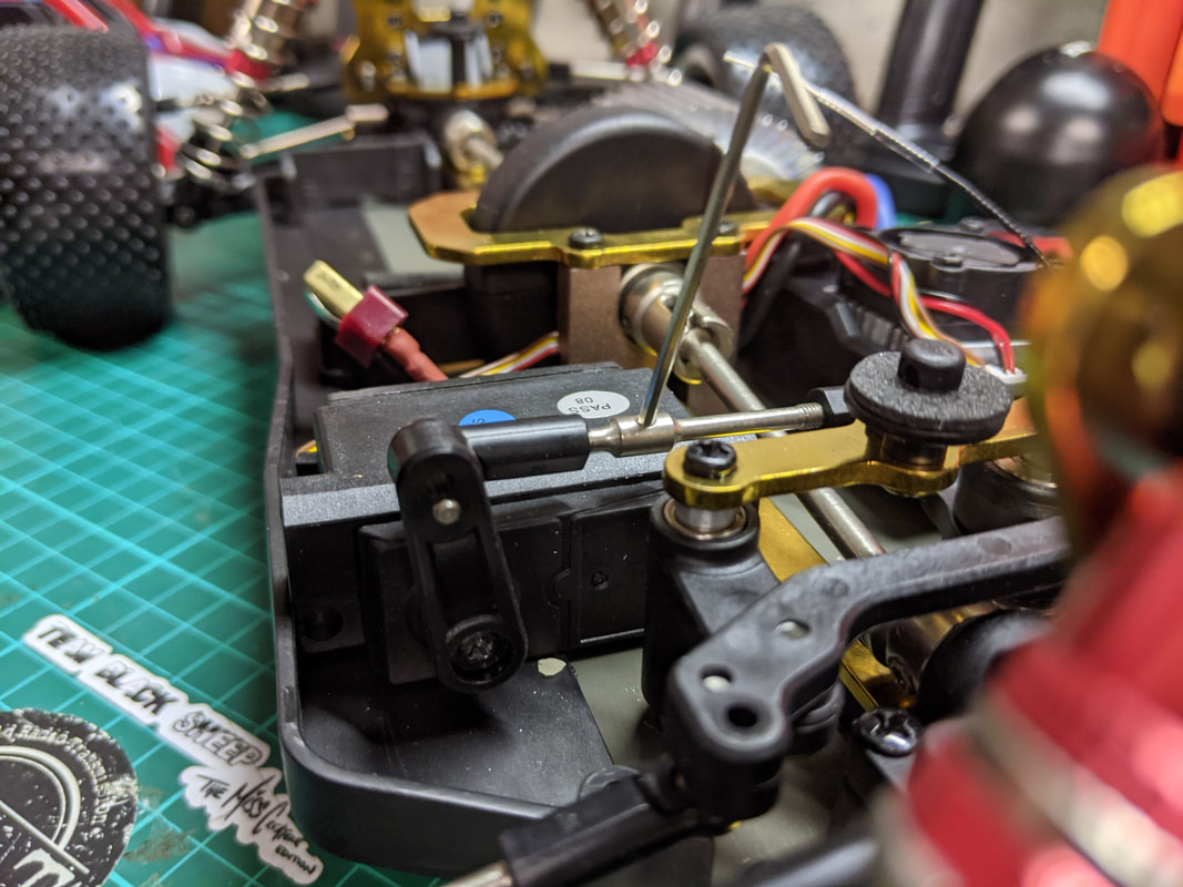
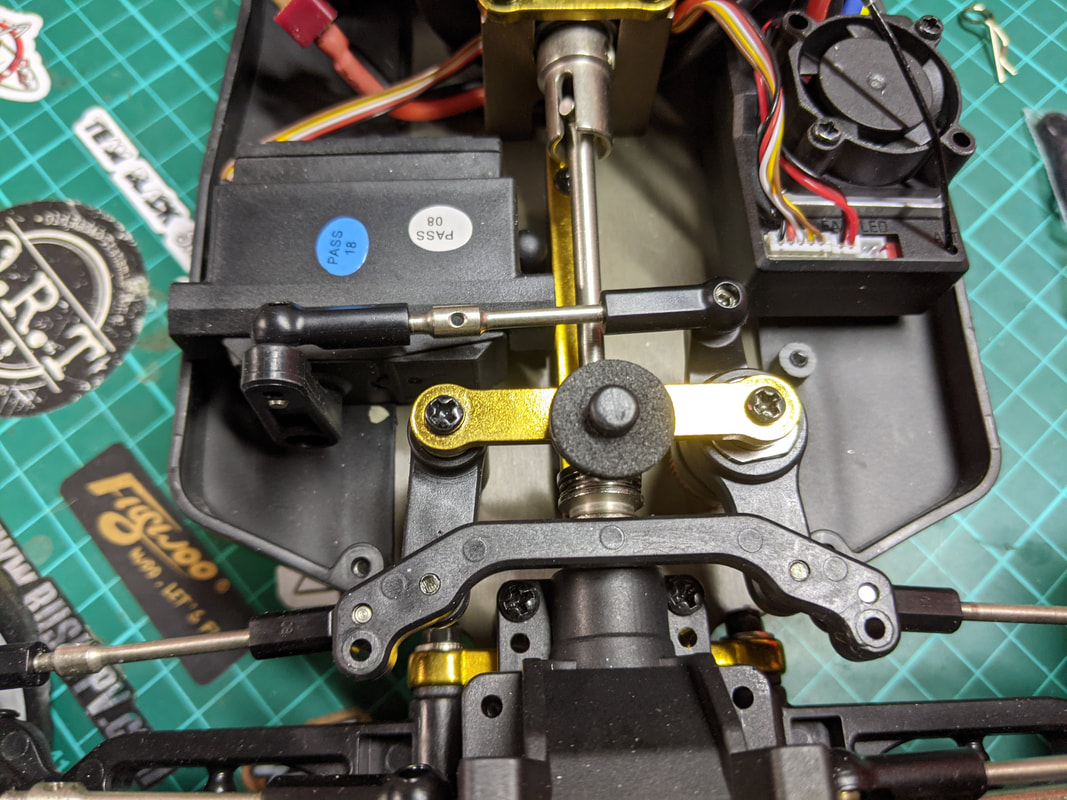
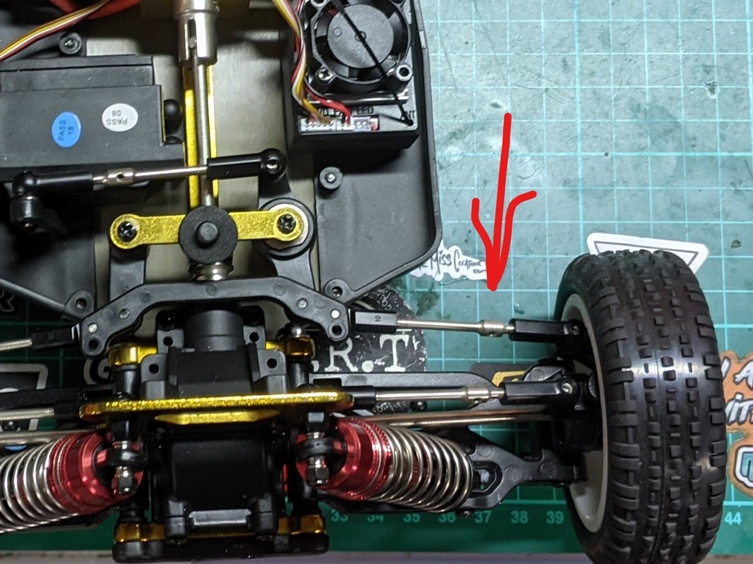
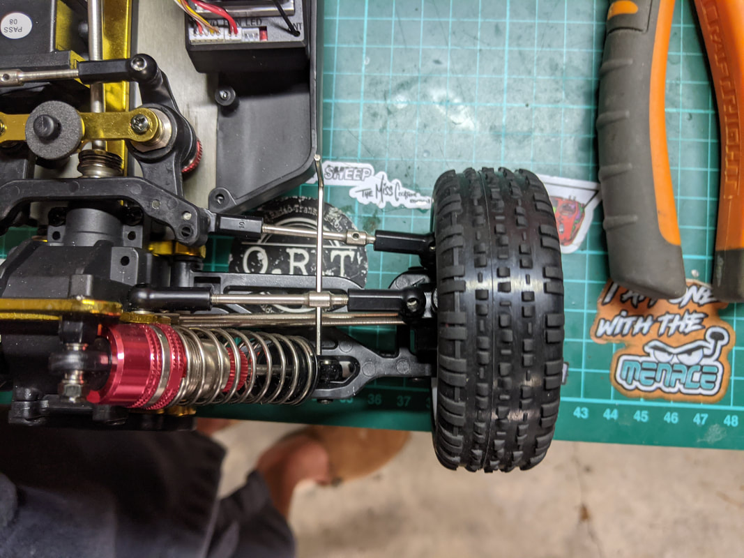
With no real fluid inside my diffs would free wheel easily and limit traction where I needed it most when offroad. Although I'd probably choose a slightly lower weight fluid next time I do get much better drive grip on low grip surfaces and more predictable drifting.
Adjust tie rods to the correct length
The tie rod are the metal bars (with black plastic ends) the connect the wheel hub carriers to the chassis. They are fully adjustable and shortening or lengthening them can change the following:
  • Camber front and rear - the angle the the wheels lean in (negative camber) or out (positive camber) at the top
  • Toe adjustment front only - the angle that your wheels point in (toe in) or out (toe out) looking from the top down
Adjustment from the factory is awful - way too much toe out and negative camber. The ideal is for a tiny bot of toe out on the front of a 4wd car (or neutral to be safe) and a little camber front and rear to help with cornering and tyre wear. Below is how to adjust:
Picture
Picture
1) This is how it came from the factory. Toe out and all of the steering mechanisms are misaligned. Yes, my slippers are super comfy.
2) First you'll need to set a reference point, that being that the steering cranks and assembly is in neutral (symmetrical) position as above. This will be the point you adjust everything around.
Picture
3) In the image above you'll see the servo horn is not pointing straight up with the steering cranks in that neutral position - this needs to be addressed...
Picture
4) Insert a small too (I used a 1.5mm allen key) into the hole in the tierod/turnbuckle and rotate either back or forth. Since each end is threaded oppositely the tierod will lengthen or shorten. In the above photo I pulled towards me to shorten. Note if the black plastic ends twist off the pillow balls the give them a small twist to release the bind and you will be fine to proceed as normal.
Picture
5) Steering cranks are now symmetrical and servo horn is pointing straight up. This should give even steering for both left and right now.
Picture
6) Now adjust the right steering tie rod to set the "toe". Aim to point this either straight ahead or allow up to 1 degree "toe out" (pointing outward). A little toe out in a 4wd car is ok because the front wheels being driven pulls them forward. The 1 degree allows for the slop in the steering mechanism to be taken up mean that under power the point directly ahead. Repeat for the left side
Picture
7) Do the same for the front upper tie rods which set the camber. Aim for around 2 degrees negative camber at the front i.e. tops pointing slightly in towards the car. Repeat for the other side.
Picture
8) Finally adjust the camber for the rear. Start with around 1 degree - ever so slightly pointing inwards at the top
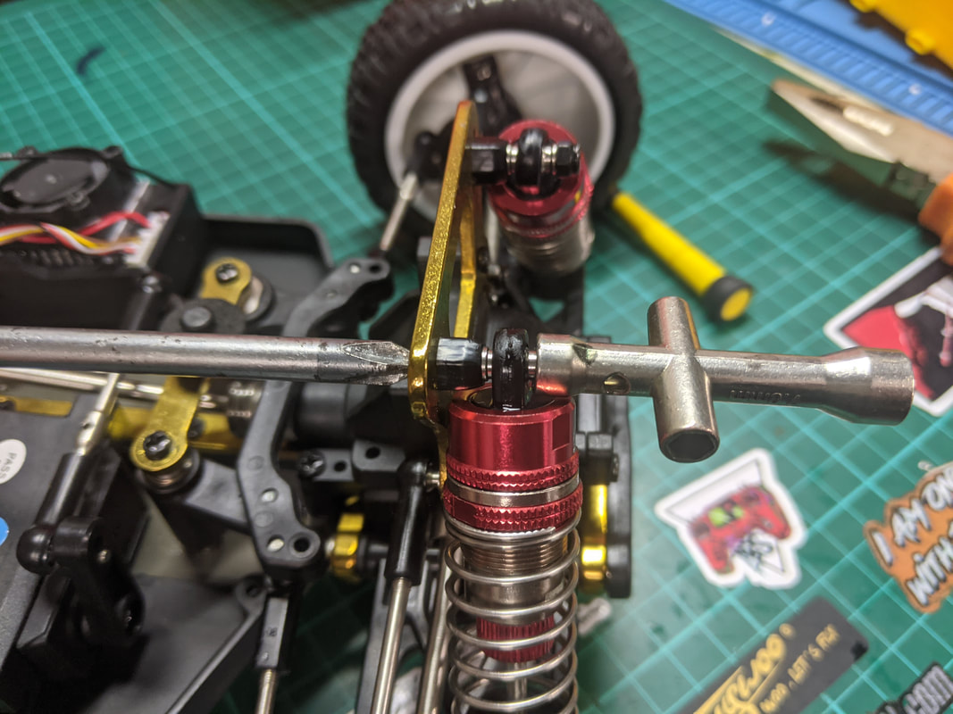
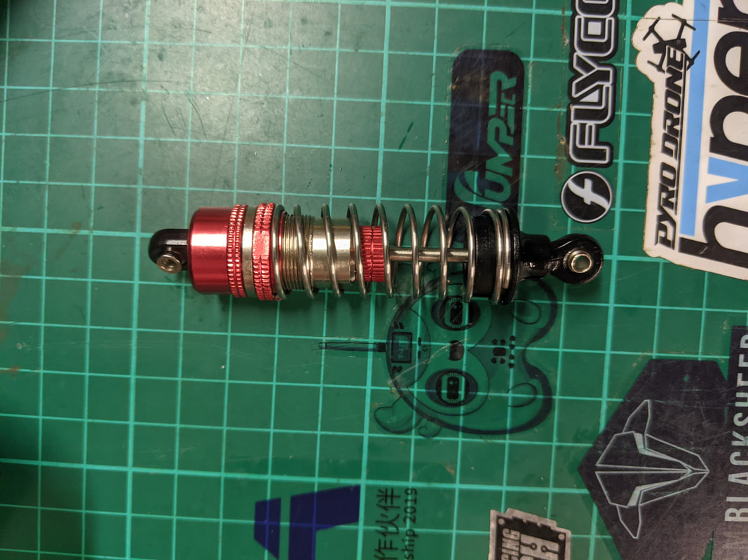
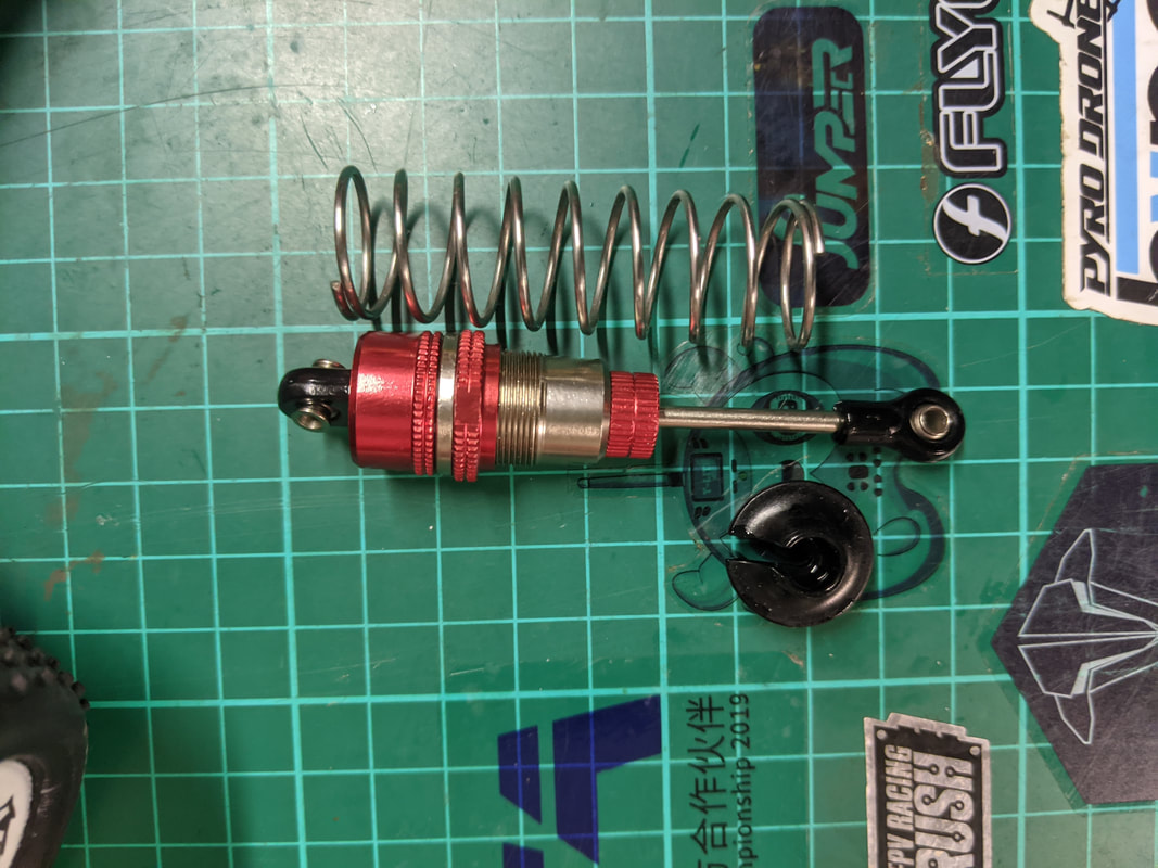
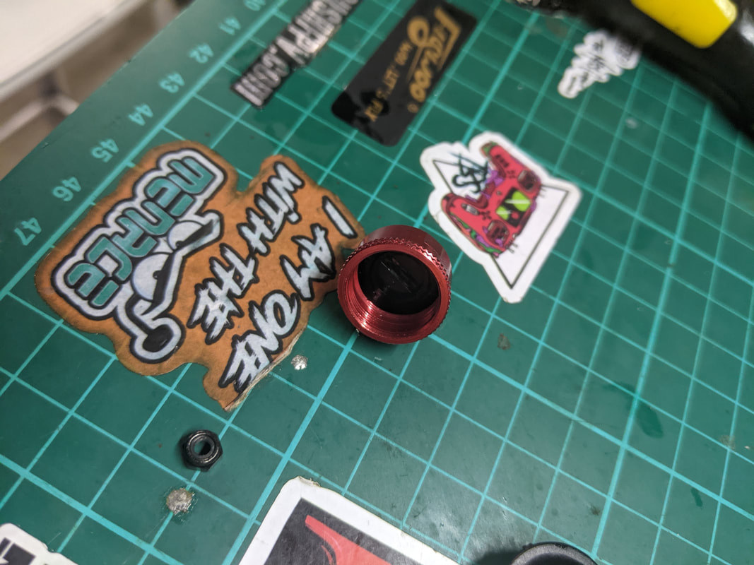
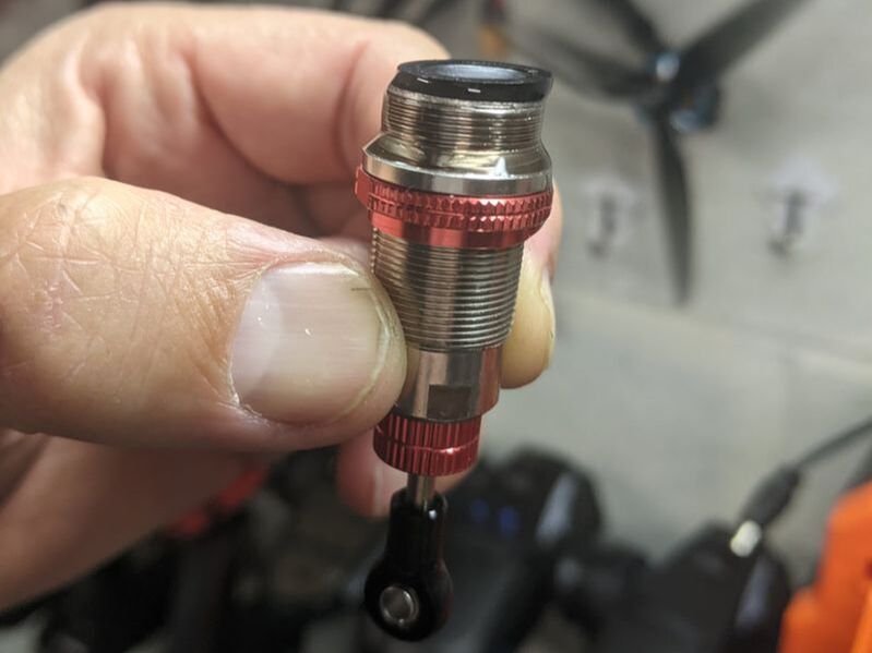
As you saw my steering, toe and camber adjustments were well out. This tuning gave me more consistent steering left and right, better straight line tracking and cornering stability plus more even tyre wear.
Correct fluid level in the shocks
When the 144001 was released it didn't have enough shock oil and dampening was a little light. Later on they had too much oil which limited travel and made the lower seals leak. So how about the 104001 now that they have those learnings? Well mine was alright - slightly low if I am picky - which I am! I topped mine up with a 30wt shock oil as below:
Picture
1) Remove the front shocks 1 at a time. To do the top you'll need a Philips screwdriver and something to hold the M3 nut while you undo it.
Picture
2) Undo the lower M3 screw as well and remove the shock absorber
Picture
3) Here is one of the front shocks removed
Picture
4) pull the spring up and remove the lower black collar via the slotted piece. Set the spring and collar aside
Picture
5) Unscrew the top cap. Don't spill it! If you have been playing with the shock like I always do, allow 5 minutes for the bubbles to escape the thich shock fluid.
Picture
6) I topped mine up with a little 30 weight oil right to the top with the piston fully down.
Picture
7) Gently remove the rubber seal from inside the top cap. It will look like this once you have removed.
Picture
8) depress the shock piston and pop the top rubber seal on. Some fluid will overflow - that is fine
9) Gently screw the top cap all the way on. Pull the piston all the way down and you should feel consistent resistance all the way down as the shock absorber does it's job. As the shaft leaves the cavity it will create a small vacuum which causes the rubber seal to flex slightly into the cavity whilst keeping a hydraulic seal. If movement range is limited or you hear bubbles, repeat steps 5) - 8).

Finally reinstall the shock and repeat for the remaining front and both rear units.

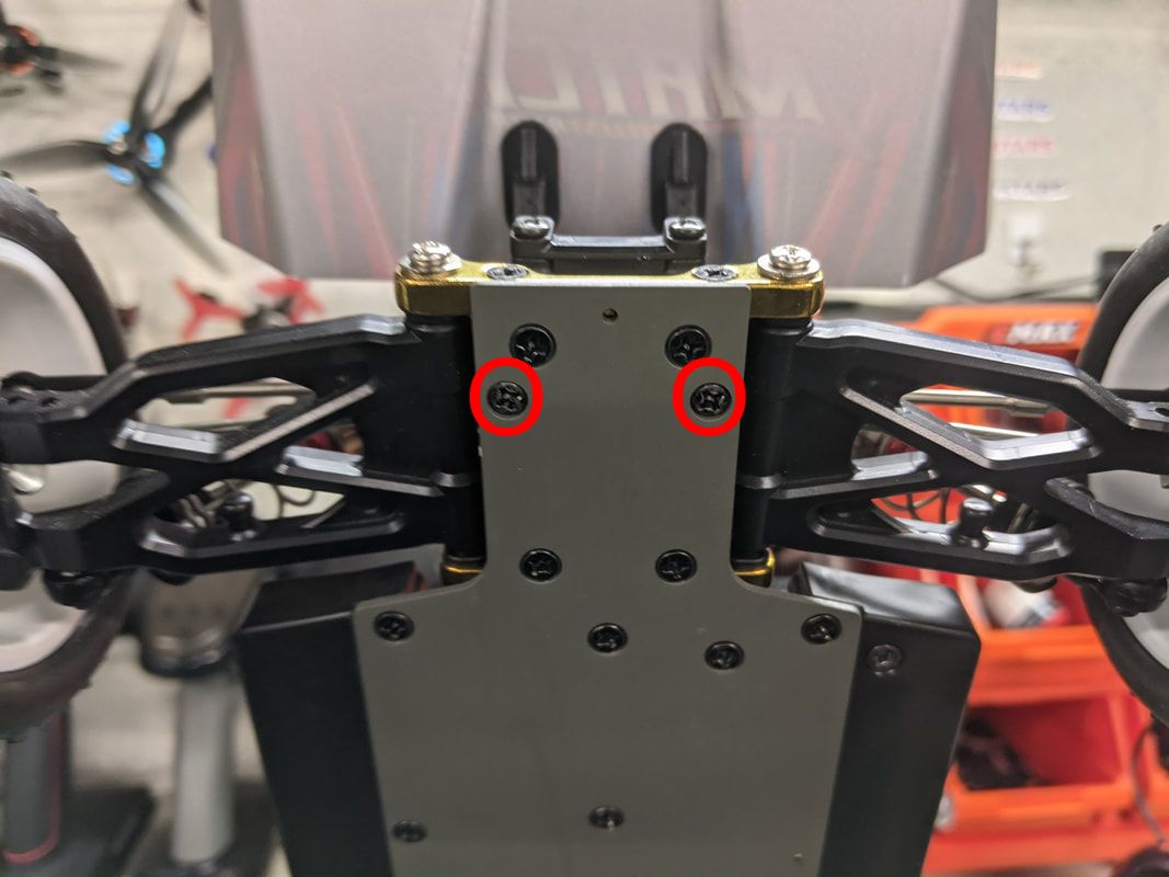
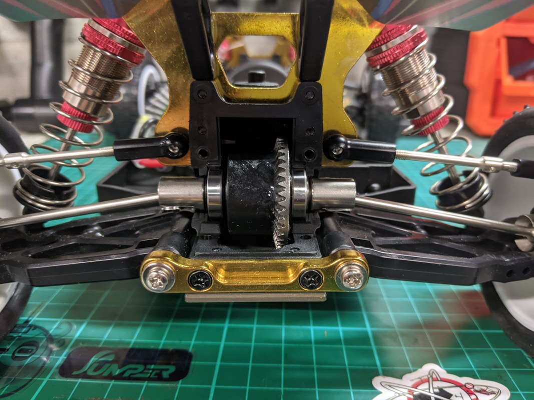
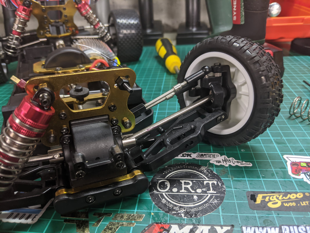
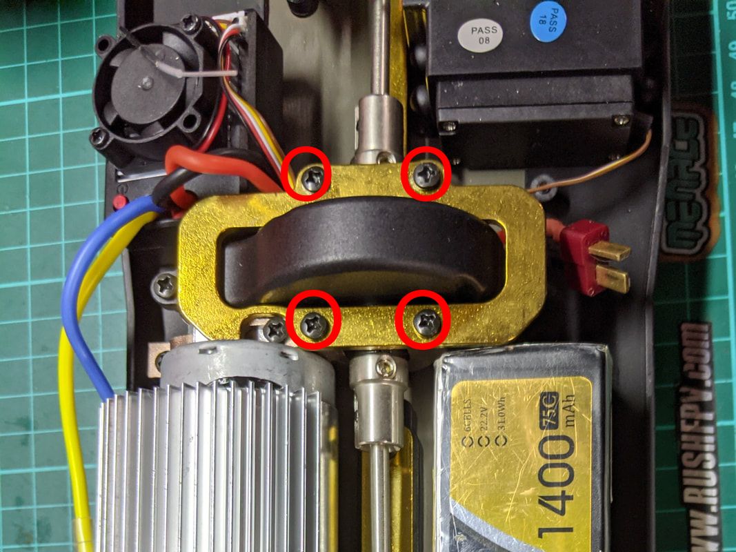
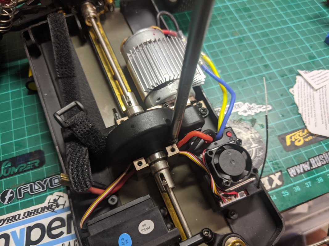
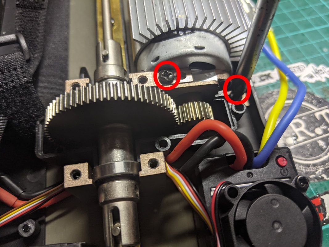
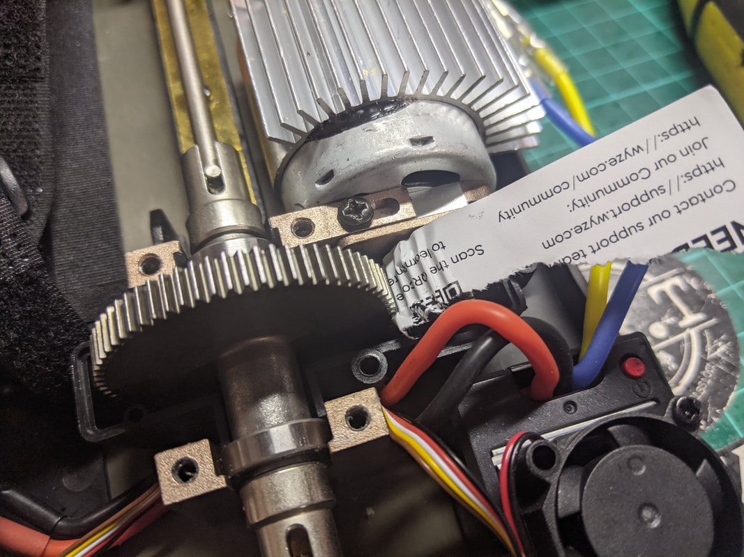
My shocks were slightly underfilled and I could have run as is but with this method I get the best and most consistent dampening possible.
Confirm gear mesh is correct and adjust if necessary
The 144001 had a fixed motor mount which was great because your gear mesh was perfect no matter what but disappointing for the advanced users because it meant not adjustment if you wanted to change pinion sizes. The 104001 is fully adjustable and my gear mesh was way too tight from the factory. This forces this pinion against the spur which creates friction and results in additional wear, a reduction in power and increase in load on the motor and electronics - not the situation you want and a really important area to fix. Below is how I set my gear mesh correctly.
Picture
1) Undo these 4 screws that hold down the gold coloured aluminium piece that keeps the spur gear in place. Use a good driver as these screws have plenty of loctite
Picture
2) Next undo the 3 screws that hold the black plastic spur gear cover on. Remove the cover and this will expose the spur and pinion gear
Picture
3) Loosen the 2 circled screws but don't remove - 1 full turn is more than enough. You'll see they go in a slotted hole. You should now be able to slide the motor in and out which will move the pinion closer and farther from the spur gear.
Picture
4) Personally I like to set the gear mesh by feel but the paper method is easier for beginners. slide a piece of regular a4 or copier paper between the pinion and spur. Pust the pinion hard into the spur with the paper between and snug down both the motor adjust screws that you loosened in step 3). This should be the gear mesh set. Rotate the paper out and it should be tightly crinkled as above and your gear mesh about right - make sure the car rolls freely to be sure. Reverse the disassembly of steps 2) and 1) and you're good to go!
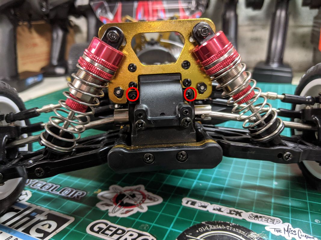
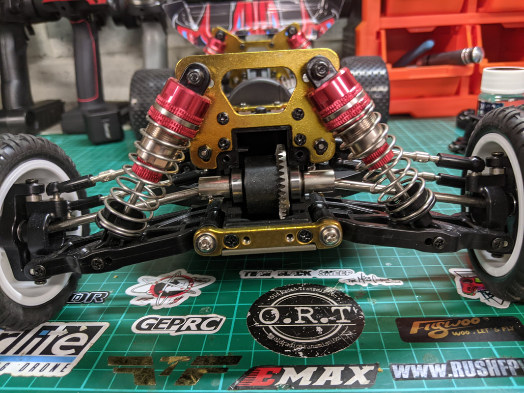
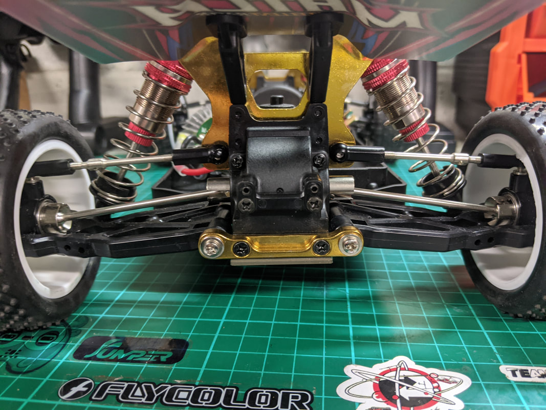
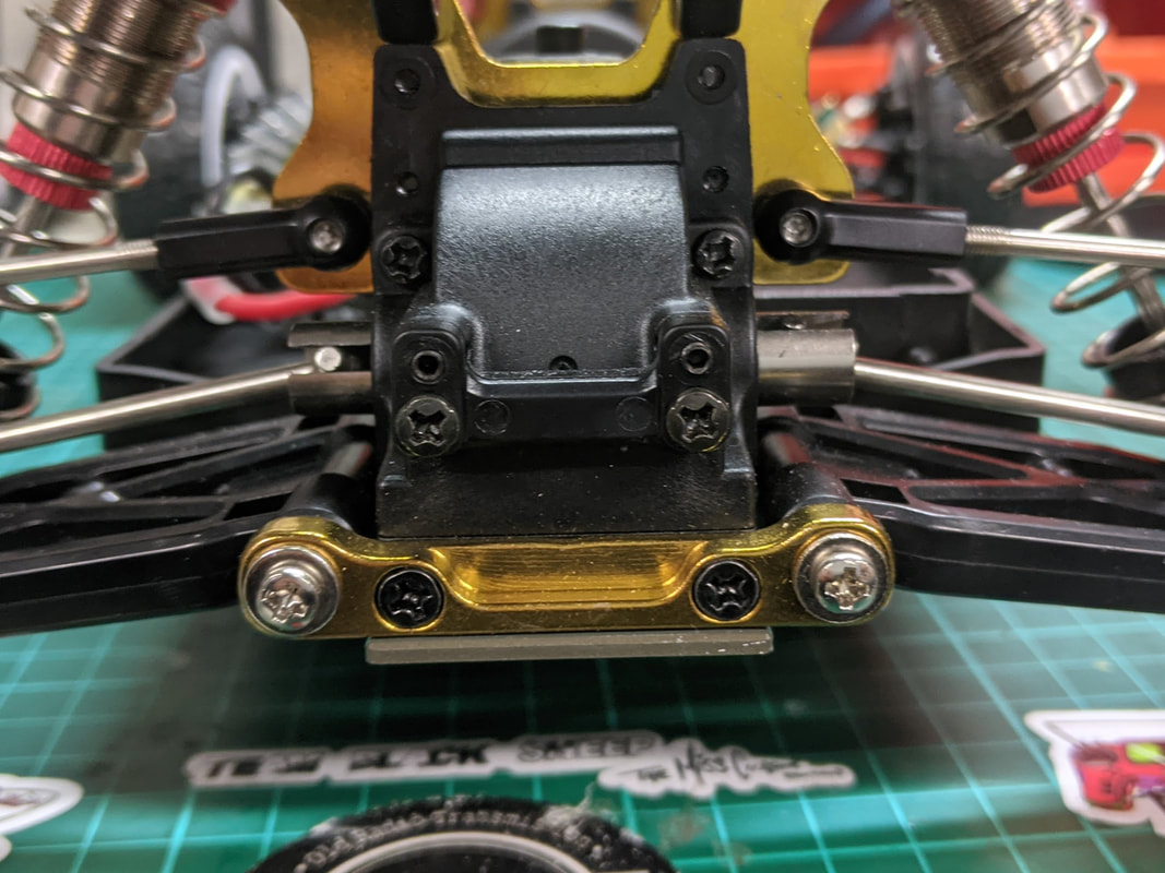
My gear mesh was too tight. with it correctly spaced as above you'd instantly get more power, better battery life and less wear.
No droop screws, no rear toe adjustment.
On the 144001 we were able to add droop screws to limit suspension travel but we do not have this option here. The only way this can be done is by adding collars between the shock piston and body as was done in this article. This does however mean disassembling the shock in order to do so. As much as I'd prefer droop screws like on the 144001 and 124019/18, setting ride height with collars in the shocks seems to be commonplace with 1/10 scale race cars, presumably because it is more accurate.
The rear arm pins resolve a lot of the strength issues from that of the 144001 including a through bolt and solid metal mounting points but takes away the adjustability. Toe in is less severe here though so I am happy to leave as is on this car - not that I have a choice!!
Picture
Unlike the 144001, the rear arms have no plastic inserts meaning can can't choose between toe in and no toe. Instead they have one piece aluminium mounts and screws rather than captive pins. This is a vastly superior design feature that was a weak point on the 144001 and 124018/9 series of cars.
Picture
Rear toe in is exaggerated by this picture and it's not too bad. It actually helps with cornering stability in the real world. Lack of adjustment here is a small price to pay for the extra durability.
What next for the 104001
I have plenty of plans for the 104001 to come which of course I'll be writing full guides on which will include:
  • Full review and comparison to the other WL Toys models
  • How to get the most performance out of the stock setup
  • Brushless upgrade guides (of course)
  • Wheel and tyre recommendation
  • Servo upgrade options
Picture
Picture
Picture
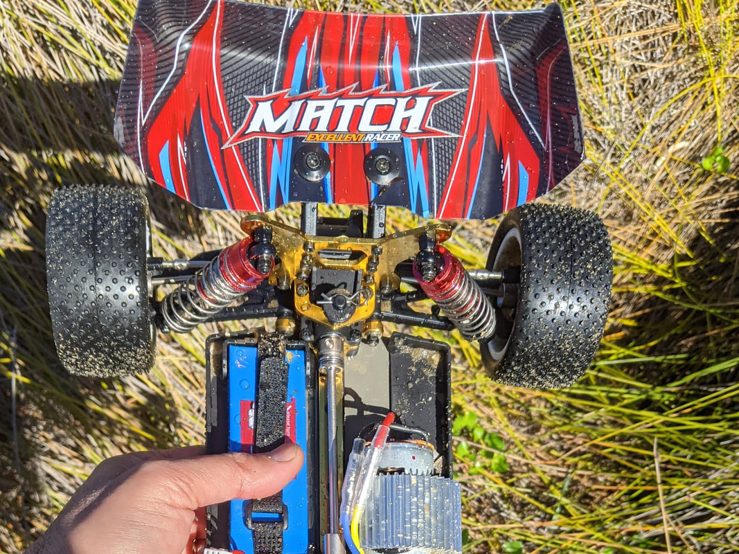
Review is coming soon and it gets a bit messy!!
Hopefully you have found this article useful, I'm focusing on making my guides and testing more technical and exhaustive so the choice is made easier for you. If you purchase via the links here or on any of my pages I receive a small commission at no cost to you which is enough to help my cover my hosting fees and other expenses related to quadifyrc.com - thanks. BTW if you are looking for some solid deals I chose my favourites in the coupons and discounts page here
Comments

    Categories

    All
    1002s
    104001
    104002
    104009
    104072
    1/10
    124016
    124017
    124018
    124019
    14209
    14210
    14301
    14302
    144001
    144002
    144010
    16886
    16889a Pro
    184016
    284010
    284131
    284161
    4s
    4 Things
    Am-x12
    Anti Roll Bars
    Balance
    Basher
    Battery
    BL3FG
    Brushless
    C24
    Charging
    Cogging
    Crawler
    D22
    D32
    Diatone
    Diatone Q25
    Drift
    Drop In
    Dumborc
    Eachine EAT14
    Eachine EC30
    Eachine EC30B
    EMB-MT
    Ex07
    Ex16
    Flyhal
    Flysky FS-G7P
    Flysky Noble Pro
    FMS
    FPV Car
    Furitek
    Goolrc
    Guide
    Gyro
    HBX
    Hbx 901a
    HS10422
    IFlight M4 AC
    K989
    LC12B1
    LC Racing
    Lipo
    Metal Parts
    Micro
    MJX Hyper Go
    Mod
    Monster Truck
    Multiprotocol
    Mx-07
    Pincone
    Pinion
    Preview
    Program Card
    Project WLCRacing
    Q33
    Racerstar
    Radiolink RC6GS V3
    Radiomaster MT12
    RC Boat
    Receiver
    Review
    Rlaarlo
    ROCHobby
    SCT
    Setup
    Sg 1602
    SG 1603
    SG 1604
    SG Pincone 1002s
    Snt
    Soldering
    Spectre
    Speed Run
    Stance
    Surpass Hobby
    Timing
    Transmitter
    Tuning
    Tyres
    Upgrade
    Vinyl
    Wheels
    WL916
    WLToys
    WL Toys
    WLToys 2428
    Wpl
    X6pm-350
    Y60
    Zd Racing

    RSS Feed

Thanks for visiting QuadifyRC.com Follow us on facebook below to get all the latest updates
  • RC Cars
  • Car of the Month
  • Quad Reviews
  • COUPONS AND DISCOUNTS
  • About & Contact