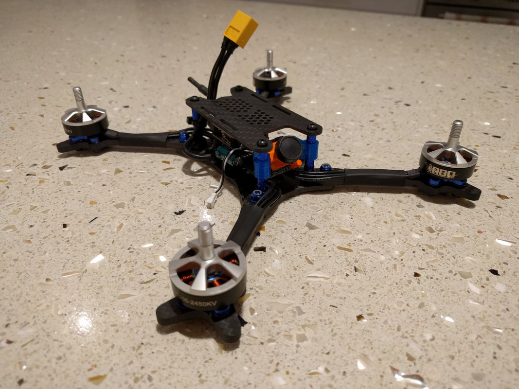
 This is the build log for my floss 2 racing 5 inch quad that is based around the HGLRC F428 TX20 Elf 20mm x 20mm electronics. In part 1 I covered the reasoning behind all of the components in the build. Although this kit does include a micro CCD camera, I ended up using it on my Leader 120 since it was slightly lighter. I'll cover the steps that can be seen in each of the photos below. Click on the pictures to embiggen.  Motors and frame. So yeah, skipped a few steps to get to this point but I was a bit excited getting it together: -Raceday quads Returner R2 2450kV motors were attached to arms using screws with loctite. Heat shrink placed over the arms with wires inside for a clean look and to keep wires away from possible prop strike or tangling. -Hyperlite Floss 2 5" frame assembled 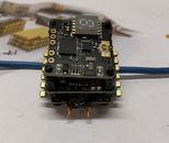 Strengthening the ESC battery pads This part is important. I've seen people mention that earlier reports of other HGLRC ESC have had VBAT pads wripped off when batteries have ejected on crashes. In addition these pads are small and I'd struggle to get a connection even with 16 gauge wire - the minimum I'd want to use on this build. The solution I used was to take some copper strand from the core of home wiring and thread as many as possible through the VBAT holes. Then twist tight and trim to about 4mm long. It's not shown in this image but then tin the pads and wire with a good hot soldering iron - I used 380°C on my TS100 soldering iron. 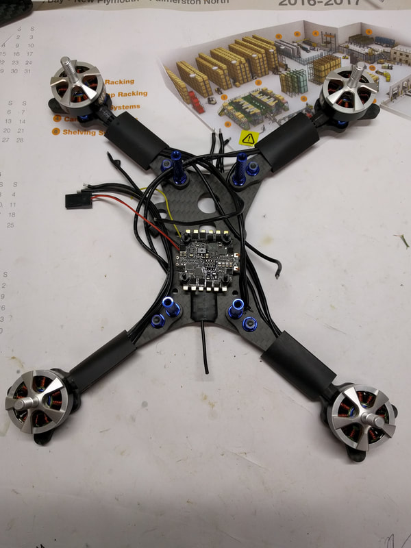 ESC and receiver mounting Here the ESC has been mounted on the supplied m2 nylon standoff which have been attched to the frame with m2 x 6.5 screws. A FS82 flysky receiver that I previously bound was heatshrinked with power and signal wires passing underneast the ESC. I'll replace this later when I upgrade to the FRSKY Taranis Q X7S. Note the orientation of the ESC. Motor pads need to go to front and back as the FC must rotate with ESC due to pin connection. If the pads go side to side then the USB port on the FC becomes inaccessable at the front or back. 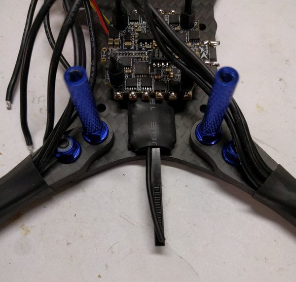 Rx antenna strengthening Shoved the end of a cable tie between reciever and heat shrink here. Added heatshrink on top of this and the monopole antenna to keep it stiff andaway from props. 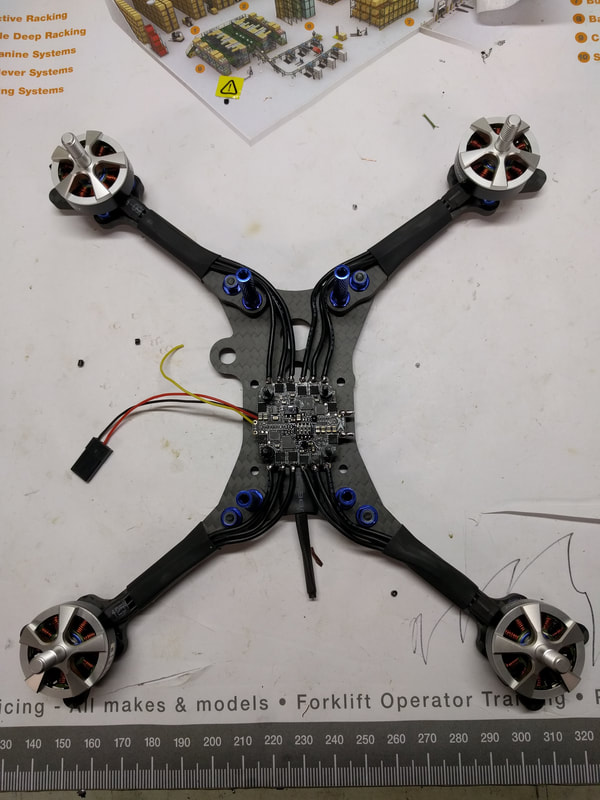 Motor wire connection Motor wires solder up to ESCs. Order is not important as this can all be changed via software in BL Heli and Betaflight.
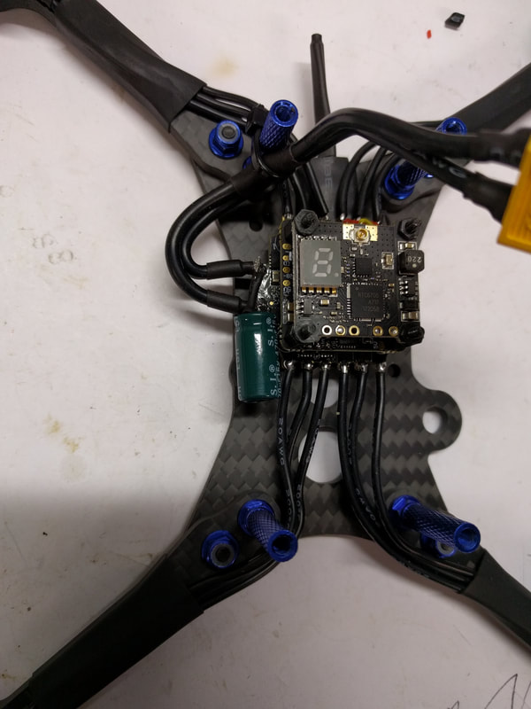 VTX wiring and capacitor 5 things in this image: -Flight controller added to stack -XT60 added with cable tie to right rear standoff for strain relief. Wires had extra heat shrink so rubbing doesn't wear the insulation off. -Capacitor added - 25VDC 470 micro farad to supress potential electrical noise -Receiver soldered to the flight controller -VTX wired and added to stack 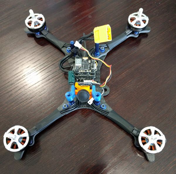 FPV camera mounting Runcam micro swift 2 added to the TPU mounts to check for size. Heaps of room! 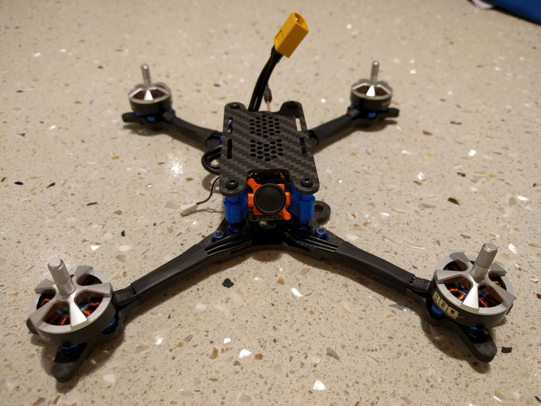 FPV camera wiring to FC Camera has been wired up here with the F428 flight controller having unique pads at the front of the board specific for the camera - 5v/ground/Vin - very clean and easy to wire. 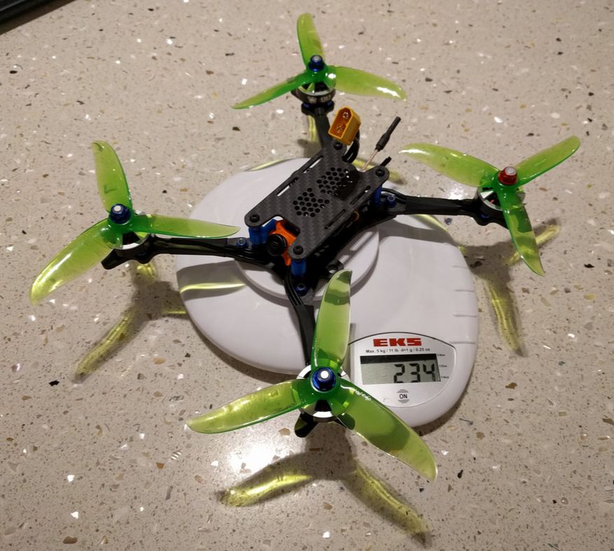 Finishing up and software updates Here is the money shot with all the software updates and changes done: -BL Heli updated to 16.3 with motors running reverse -Betaflight updated to 3.2.1 with Omnibusf4 target -Top plate and props added -OSD turned off in swift micro due to betaflight OSD Summary
In summary this was head and shoulders the easiest build I have done thanks largely to the HGLRC XJB F428 TX-20 Elf electronics. Why? No wires between ESC and FC, all pads for the vtx at the back, all pads for the camera at the front and ESC, FC and VTX fit in a nice small, light stack. The only down size was the small VBat pads which I think I have a good solution for however only time will tell. The build is light and well enclosed so should be strong. Everything fired up perfectly first time with no smoke which is always a bonus. So far as the build is concerned I am very pleased with all the components I've chosen here but I really need to put them to the test in flight to be sure.
9 Comments
Kory
28/10/2017 10:55:10 am
Would love to hear a follow up with info on how the stack is holding up over time and crash survivability.
Hi Kory. Good question, am just about to do an update.
Kory Chang
31/10/2017 06:06:47 pm
oh that's not good, I have a very similar setup with the same stack, on the original floss and sunnysky 2204 motors. first stack, VTX burnt up only after about 30 sec. and the esc for motor 1 died after about 6 packs, it just stuttered and wouldn't spool up.
Hey Kory. I think I've been reading about yours on the thread I started on RCGroups? HGLTEch emailed me back and said capacitors should be added to the ESC (as I did in this build). I clarified my question to them so I can understand if this stack is appropriate for this type of build or not.
Kory
1/11/2017 09:36:46 am
Ah yea, I've been posting on RCGroups so probably was me(fretman).
QuadifyRC
6/11/2017 10:22:18 am
Hi Kory
A capacitor in general will limit voltage spikes (high and low) and so place less stress on any electrical component and in the case of the vtx a better regulated power supply will mean less interference. For all components additional capacitance will mean longer life. Being a small board there may not be much capacitance on the F428 ESC and so perhaps why they recommend and external one. 17/5/2024 09:51:42 am
As per the top-most cleaning companies, lambswool duster are probably the effective tools to fix the good sized kitchen sections. So, whether your house is in a flat or house, this particular tool are generally beneficial if you want to clean typically the dirt not to mention dust without any difficulty. And, the lambswool dusters differ from the various regular dusters. Besides that, you will reuse this unique duster for the purpose of future usage. To tidy the fragile areas prefer kitchen bins or storage, lambswool duster could be ideal. Leave a Reply. |
Archives
August 2018
Categories |
 RSS Feed
Thanks for visiting QuadifyRC.com Follow us on facebook below to get all the latest updates